
Service
Design & Development
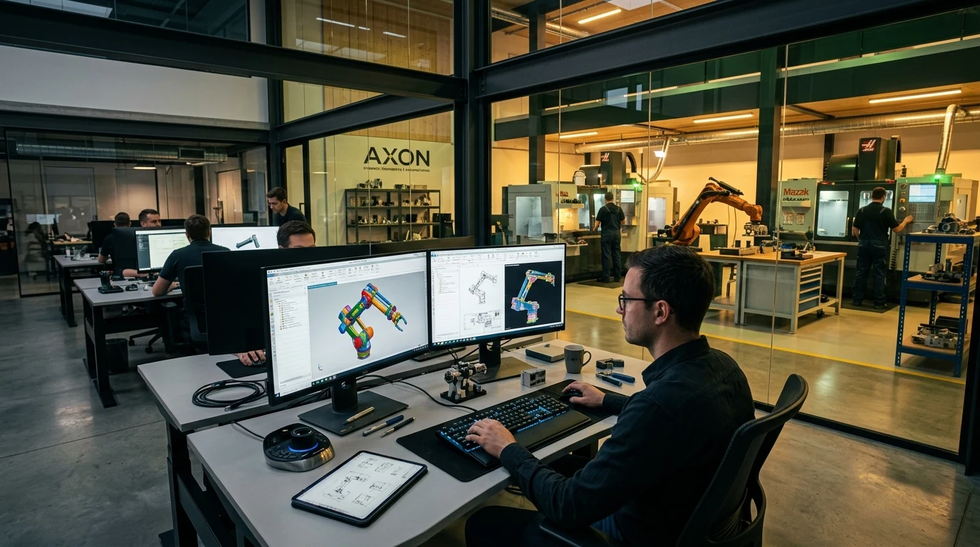
From napkin sketch to verified 3D model — our engineering team translates your production challenge into a precisely engineered automation solution.
Complete Engineering Design
Our design team combines deep SPM domain knowledge with modern engineering tools — delivering designs that are not only innovative but manufacturable, maintainable, and built to last.
Every design goes through multiple review stages including concept, preliminary, and detailed design — with full customer involvement at each gate.
- 3D CAD modelling in SolidWorks / CATIA
- Kinematic simulation and motion analysis
- Finite Element Analysis (FEA) for structural integrity
- Design for Manufacturability (DFM) reviews
- Electrical & pneumatic control system design
- Custom jig & fixture engineering
- Prototype validation and pre-production sign-off

Our Design & Development Process
From initial technical scoping to validated 3D digital twins and shop-floor manufacturing runoff — every custom automation project passes through 4 strict engineering quality gates.
Requirement & Kinematics Scoping
Detailed review of component CAD files, target cycle times (CPK/CMK indices), space envelope constraints, and safety interlocks.
- ✓ Cycle Time & OEE Model
- ✓ Factory Floor Envelope
- ✓ Component Constraint Matrix
3D Concept & Motion Simulation
Multiple 3D CAD concept models built in SolidWorks / CATIA with pneumatic, servo, and hydraulic actuation trade-off simulations.
- ✓ Multi-Concept 3D Models
- ✓ Kinematic Motion Simulation
- ✓ Actuator Sizing & Torque Study
FEA Simulation & Electrical Design
Finite Element Analysis for structural deflection and dynamic loading, EPLAN electrical schematics, and complete manufacturing BOM generation.
- ✓ Structural FEA Stress Report
- ✓ EPLAN Electrical & Pneumatics
- ✓ 100% Traceable Production BOM
Virtual Runoff & Sign-Off Gate
Pre-manufacturing 3D collision check, digital twin PLC sequence validation, and final 2D manufacturing drawings release with client sign-off.
- ✓ 3D Interference & Collision Check
- ✓ Digital Twin PLC Sequence Run
- ✓ Drawing Release for Production
Frequently Asked Questions
Everything you need to know about our engineering design process, software capabilities, IP protection, and international compliance standards.
Our engineering department works natively in SolidWorks, CATIA, and Autodesk Inventor for parametric 3D CAD mechanical modeling. For structural, thermal, and dynamic stress analysis, we utilize ANSYS and SolidWorks Simulation (FEA) to simulate deflection and cyclic fatigue before manufacturing. Electrical and pneumatic automation schematics are authored in EPLAN Pro Panel.
Yes. Many of our clients approach us with initial hand sketches, component STEP files, or legacy 2D drawings. Our engineering team conducts comprehensive Design for Manufacturability (DFM) reviews, calculates kinematic forces, sizes actuators/motors, and generates complete parametric 3D models and detailed manufacturing drawings with GD&T specifications.
We operate under strict mutual Non-Disclosure Agreements (NDAs) prior to receiving any component drawings or project briefs. All project files, 3D CAD assemblies, EPLAN schematics, and PLC source code are stored on encrypted, access-controlled local servers. Upon final handover, 100% full design ownership, source codes, and CAD models belong entirely to the client.
We follow a structured 4-Gate Design Review Methodology. At each milestone (Concept, Preliminary 3D CAD, Detail Engineering/FEA, and Pre-Manufacturing Validation), our project managers host interactive 3D virtual walkthroughs and provide formal gate review documents for your engineering team’s sign-off before raw material cutting begins.
Absolutely. We design automation systems compliant with CE Machinery Directive (2006/42/EC), EN 60204-1 (Safety of Machinery - Electrical Equipment), ISO 12100 (Risk Assessment), and UL 508A standards upon request. Our electrical designs feature dual-channel safety relays, light curtains, and category-3/4 SIL-rated safety interlocks.
Yes. Upon final project sign-off and delivery, we provide a complete Technical Dossier including editable STEP / IGES 3D files, 2D PDF/DWG manufacturing drawings with complete Bill of Materials (BOM), recommended spare parts lists, and electrical/pneumatic schematics.